| Ref.No. | Part No. | Description | Qty. |
|---|---|---|---|
| 1 | 65 | Bracket. Standard Universal Mount | 1 |
| 2 | 97 | Screw. 8-32 Flathead Tamper-Resistant | 2 |
| 3 | 98 | Wrench. 3/32 Allen | 1 |
Tools Required For Assembly
1: 3/32 Allen Wrench (supplied with mounting kit).
PERMAGLO® SIGNS
STANDARD UNIVERSAL MOUNT ASSEMBLY
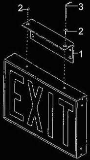
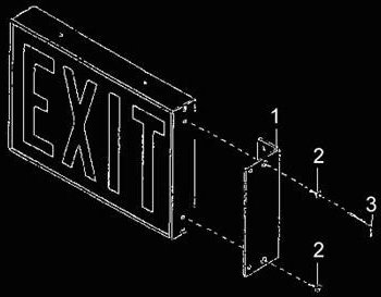
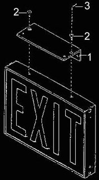
AND MOUNTING INSTRUCTIONSTo aid you in assembling the standard universal mount for the model PERMAGLO EXIT SIGN. Refer to Fig.1 (wall surface installation), Fig.2 (wall end installation) or Fig.3 (ceiling surface installation) of the illustrated parts breakdown.
INSTALLATION OF THE STANDARD UNIVERSAL MOUNT ASSEMBLY
NOTE: Prior to attaching the standard universal mount bracket to the exit sign in one of the three possible mounting positions, it is recommended that the installer take careful measurements. The bracket can be used as a template for marking the wall or ceiling attachment holes. To further aid the installer, a level should be used to ensure an aesthetic and eye-pleasing mounting.
CAUTION: For all installations except the wall surface mounting, steps 1 and 2 apply. For wall surface mounting, follow steps 3 and 4.
1. Remove the two plastic caps covering the mounting holes on the exit sign. Attach the standard universal mount bracket (1) to the exit sign with the two 8-32 countersunk screws (2). Tighten these screws securely with the enclosed 3/32 Allen wrench (3).
2. Attach the exit sign/bracket assembly to the ceiling or wall using your own attachment hardware.
3. Mount the standard universal mount bracket (1) to the wall using your own attachment hardware. CAUTION: In wall and surface mounting the exit sign, especially close to the ceiling or other obstructions close to the top of the sign, be sure to leave enough space between the sign top and the obstruction. This will permit you to insert the 8-32 screws (2) and to tighten them with the Allen wrench (3).
4. Attach the exit sign to the mount bracket (1) with two 8-32 screws (2). Tighten these screws securely with the enclosed 3/32 Allen wrench (3).
Parts List
Tools Required For Assembly |
Fig.1: Wall surface mounting
|
||||||||||||||||
|
Fig.2: Wall end mounting
|
Fig.3: Ceiling mounting
|